
Oilfield electrification, onshore and offshore is one of the main themes of the energy transition. The primary definition of electrification in oil and gas operations refers to converting or replacing generators and other equipment running on diesel or other hydrocarbon fuels with equipment that runs on electricity, usually supplied by local utilities.
Reducing the cost and carbon emissions of oil and gas production through electrification are not mutually exclusive goals. However, a piecemeal approach will may fail. Maximising electrification’s impact in the oil and gas industry necessitates adopting new technologies if we wish to enable more sustainable operations while simultaneously driving efficiency, reliability, and performance.
The majority of drilling rigs and platforms and other production infrastructure, including FPSOs use diesel or natural gas turbines which result in high direct fuel costs and greenhouse gas emissions. For offshore production platforms and other permanent facilities, electrification is an attractive option if low-carbon electricity can be made readily available, for shoreside or fixed and flaring wind. Permanent cables can be installed with conversion equipment between the source and the various power consumers thus eliminating the need for fuel resupply.
For offshore operations, renewable electricity can be transmitted from the onshore grid to the installation if within reasonable distance, but more likely, generated locally via fixed or floating offshore wind turbines and transferred across fields. Similarly, for onshore fields, electrification can mean connecting to a low-carbon grid source or local renewable source. The options to decarbonize onshore energy sources are more numerous, but so are the number of locations requiring power. However, there are challenges and costs in the conversion or replacement of some types of equipment.
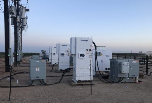
Landrigs
Most landrigs have SCR drilling packages (i.e. DC drives). DC drives onshore usually have AC line reactors to comply with the utility requirements. This is rarely the case for both landrigs and MODUs.. This causes both technical and historical problems and presents challenges when during the electrification conversion.

Many landrigs have SCR drilling packages. These require experience and special techniques when using active filters
From the utility perspective, the THDu, THDi and DPF requirements must be complied with. Power factor correction must be installed for SCR based power system. This can be via conventional capacitors based or electronic VAR control, the latter is physically smaller.
Due to their very large and bulky size, series passive filters, are not really a candidate for retrofitting, as each SCR would have to be connected to its discrete filters.

1600kW series passive filter (NEMA3R)
To reinforce this point, one 1100kW series passive filter can be replaced by 4 x 150A SiC (silicon carbide) active filters in parallel of total dimensions 520H x 400W x 500D mm) in bookcase install mode. Total weight 100kg. For comparison, in 1100kW passive filter as shows weighs around 1700kg each. Due to their size, SiC active filters can be accommodated easily.
The THDu and THDi can be controlled by high performance SiC active filters but due to the lack of AC line reactors presents other problems. Installing active filters without sufficient AC line reactors can result in destruction of the active filter’s onboard carrier filter passive components (i.e. active filters usually switch at between 10-20kHz. SiC versions up to 100kHz and higher) suppression circuit (i.e. IGBT switching frequency passive filter) and failure of the active filter unless special techniques are adopted. This is due to the significant high frequency energy within the voltage notches as can be seen below.
Sample voltage and current waveforms below (one phase shown for clarity) plus the voltage spectra showing significant high frequency energy within the voltage notches.

L1 - Line and phase voltages plus phase current. ‘Ringing’ at current zero crossover due to stray capacitance.

High frequency voltage notching harmonics due to lack of AC line reactors
In theory, series passive filters for harmonic mitigation could be retrofitted to EACH SCR but these are very large and would be unlikely to be accommodated in the given space (which would have to be shared with PFC system and other equipment). Therefore, where AC line reactors are not, or cannot be, installed, special techniques are required to attenuate the high frequency notching voltage harmonics such that they cannot damage the active filters and other equipment.
Artificial Lift
Artificial lift, as far as electrification is concerned, mainly comprises ESPs (electrical submersible pumps) and sucker-rod pumps. As per landrigs, artificial lift systems must comply with rules of the utility they are connected to, especially regarding THDu THDi and DPF. Since these systems comprise AC VFDs, the DPF compliance is much less costly compared to phase controlled SCR DC drives.

Sucker rod pumps have lower kW requirements than ESP and are excellent candidates for SiC active filters which, due to their high kW/mitigation ratio (280kW/150A) can be easily accommodated in switchboards and E-houses
The historical method of harmonic mitigation for ESP VFDs has, over last 20 years, has been series passive filters. They offered adequate THDi performance, were rugged electrically and environmentally and could operate at the wellhead in temperatures to 55 deg. However, with oilfield electrification, these large and bulky series passive filters and will largely be replaced by active filters and more advanced ‘clean power’ PWM VFDs, as they may be deemed too large and bulky for installation in E-Houses.
See example of the comparison of 8 x 200kW series passive filters (IP20) and SiC active filters. The latter require almost 17 times less space than series passive filters for the same 1600kW of mitigation.

In addition to providing harmonic mitigation, active filters can also control the DPF via reactive power injection (lead or lag) as required by the utilities. The THDu, THDi and PFC can also be achieved with an appropriate mix of active filters and SVGs.

Global harmonic mitigation/PFC for ESP VFDs utilising modular or standalone SiC devices
Oilfield Power Quality
– Continuous power quality monitoring
In the context of oilfield electrification, power quality is extremely important due of the increasing complexity, size and interconnection of electrical networks which oilfields and landrigs and their non-linear drive loads are/will be connected to. In addition, it gives crucial information on the connected loads (ESP, sucker rod pumps, landrigs et al), including prior warning of harmonics and PQ problems such as the impending failure of diode in one phase of large 6 pulse VFD as show below.

Impending diode failure(s) on 6 pulse PWM VFD
In order to connect to utilities, legal contracts must be signed with the consumer which requires compliance with local PQ rules and international standards, for example the current IEEE 519. The salient PQ requirements include THDu, THDi and DFP (displacement power factor – not PQ). However, the utility has also a responsibility to oilfield consumers to provide an acceptable level of PQ, usually under, EN60150, “EU Product Standard for Voltage Supplied by Public Utilities”.
It has to be stated that continuous PQ monitoring is essential to monitor the utility supply to the consumer AND to ensure compliance with their rules and regulations, which if non-compliant can result in penalties and/or disconnection. The data captured is crucial in the event is disputes with the utility. Any disturbances from the utility can have a serious impact on the oilfield equipment and associated losses.
As an option, contract remote monitoring of oilfield PQ may be available. For more information please refer to the Continuous PQ Monitoring section for more information click here….
– UPS for PWM VFD DC bus ride through

During utility network power disturbances such as voltage dips/sags, brown-outs, reclosure events or short term loss of supply, the energy flow for the artificial lift and other processes are interrupted, or at least limited, if very short term,
Energy is stored in the PWM VFDs DC bus but can be dissipated in 1-3 cycles (i.e. determined by the motor loading) as the IGBT inverter supplies the motor with power. Once DC bus voltage reduces to a determined voltage, the VFD will trip on ‘undervoltage, DC bus’.
Power interruptions to the processes can be extremely expensive, Therefore, on problem utility networks and/or oilfield sites, the installation of VFD DC bus ride through systems to protect the processes may be considered, their cost being much less than the losses. The use of supercapacitors, electrolytic capacitors or batteries is determined by the application.

Typical UPS ride through for oilfield PWM VFDs
– EMC & EMI
Note that “Power Quality” is associated only with the interaction of the utility supply, their network and their oilfield and other consumers. Any concerns or problems between, for example, the VFD output to a motor, can be classed as EMC/EMI. These can be associated with excessive du/dt, common mode voltage and current and cable resonance (‘standing waves’).
An example of the interaction between the line and common mode voltages, phase and common mode currents on a PWM VFD is illustrated below.

Common mode voltage paths on 6 pulse PWM VFDs

Typical common mode voltage waveform (1.26kHz)

CMV trend of drilling barge with monitoring disruption and corrosion issues

PWM VFD IGBT package catastrophically destroyed by misfiring due to CMV
Excessive common mode voltage can adversely affect susceptible and sensitive control and monitoring equipment and including other VFDs. The associated common mode current is renowned for destroying and/or destroying motor bearings via high frequency micro-arcs of current. This can include bearings of fixed speed motors connected to the ground as PWM VFDs.

Common mode current paths in PWM VFDs with shielded cable

Typical common mode voltage waveform (1.26kHz)

Bearing fluting, resulting from common mode current
– Future of ESP oilfields under electrification ?
There are number of power conversion technologies around which could have a very considerable impact on the industry but which has not yet considered them for various reasons. That is understandable given its very conservative nature. One of those technologies is Resonant Link, a soft-switching technology.
Illustrated below is visualisation of an oilfield DC ring main provided by Resonant Link active AC-DC transformers power the IGBT inverter sections of PWM VFDs. Note that all the VFD will still require sinus filters and output MV transformers. This could be applied to land oilfields, offshore platforms and FSPOs.

Visualisation of an oilfield DC ring main provided by Resonant Link active (AC-DC) transformers supplying PWM IGBT inverter modules
Utilising the same Resonant Link technology, very significant cost, space and energy savings can be made via the ESP VFD variant, where both the input and output voltages and currents are sinusoidal (e.g. <1% THDi), with extremely low du/dt levels, zero common mode emissions, and since the output voltage is sinusoidal, no issues with long cable lengths. All functions normally associated with a PWM ESP VFDs ‘strings are carried out within the VFD, including MV output voltage transformation and adjustment.

Typical PWM VFD ESP system

Resonant Link ESP VFD compared to 6 pulse PWM VFD system

Basic schematic of Resonant Link ESP VFD with core reset control. Range of input and output LV and MV voltages available
The cost and physical size of this VFD is a fraction, compared to conventional ESP VFD ‘strings.’ which it totally replaces, with the bonus of an ‘overall efficiency’ increase of 12-15%, depending on loading, due to ~98% overall efficiency across the load range.
This technology is ‘soft switching’ and offers multiple applications to the oil industry, onshore and offshore, including active transformers which transform AC and/or DC voltages, for example, for MV DC transmission to subsea pumping stations or supplying platforms from floating or fixed windfarms as part of decarbonising the industry.
A visualisation of an oilfield utilising multiple Resonant Link ESP VFDs is shown below. Note the absence of any sinus and common mode filters, MV output transformers or input harmonic mitigation. A bonus is the cost and physical size compared to conventional PWM ESP systems all additional equipment they need to function. The power density of Resonant Link ESP VFDs in 3.2MW to 5.5MW per cubic meter, depending on whether LV or MV operation. This equates around 15% of volume comparable PWM based systems.

Visualisation of an AC ring main connected oilfield with multiple Resonant Link ESP VFDs
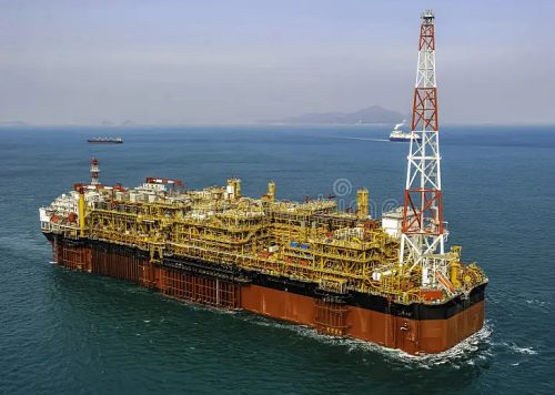
Production platforms, FPSOs and MODUs
– The importance of attenuation of background THDu
Offshore production platforms, FPSOs and drilling rigs have many large VSDs on ESPs, gas compressors, fans, pumps and other applications. This can result in background harmonic voltage (THDu) levels which far exceed the design of the installations and the harmonic recommendations which govern their use. This excessive THDu can often reach levels which adversely affects both operations and safety both on MV and via LV transformers.
Excessive THDu can interfere with monitoring and protection systems and all other equipment including electric motors, especially fixed speed explosion motors where under certain circumstances, these motors may be potentially dangerous.

THDu at 690V due to background harmonic distortion on 11kV to 50th. (26.74% THDu)
Excessive THDu above was due to external background THDu from MV (or from LV sources). This contaminates LV supplies, disrupting monitoring and control equipment and damage equipment. This includes fixed speed explosion proof motors. Based on the example above, the rotor temperature was estimated to be in the order of 35-40% higher compared to sinusoidal operation, including the rise due to skin effect.
In the context of explosion motors, of all protective concepts, this level of rotor heating does give serious cause for concern regarding the motor temperature class, the integrity of bearings and the flameproof gaps in Exd “flameproof” motors.
It is of paramount importance therefore that action is taken to significantly reduce the background THDu, especially on LV supplies where the majority of susceptible equipment is located.
An offshore application for Ultra SiC active filter voltage control for attenuation of background THDu from MV supplies is illustrated below. The salient non-linear loads on the DP semi-submersible rig were eight quasi-24 pulse thruster VFDs and a common DC bus drilling package. During operations, the average THDu appearing on the LV supplies (440V and 110V), which also fed lighting and other transformers was captured at 13.9-14.1%. This excessive THDu (on an installation designed for <8%) resulted in continual damage and disruption to susceptible and sensitive LV equipment, most of which was only designed to withstand <5% THDu. LV THDu, after treatment showed ~4.3%.

Example of active filter voltage control on a semi-submersible drilling rig.
– Powering Platforms from Fixed and Floating Offshore Wind
Oil companies across the world have ambitious plans to reduce their combined 45% of anthropogenic GHG emissions, the majority of which due to gas and diesel power generation on offshore installations. Over recent years, floating (and fixed) offshore wind power has become viable and competitive with energy prices currently paid by offshore oil & gas operators.

Currently, conventional electrical power transmission systems are being considered to connect the windfarms to the platform(s). They have innate disadvantages for these applications. However, the introduction of patented Resonant Link technology, whose performance, physical size, recued cost and lack of additional equipment required for conventional systems (and large offshore structures to house them), may favour the use of Resonant Link technology, even for short distances.
See visualisation of five small offshore platforms being supplied from fixed or floating wind farm by Resonant Link transmission system.

Five small offshore platforms being supplied by a Resonant Link transmission system

Inversion (DC to AC) at platform(s) after 150kVDC transmission