Variable frequency drives
In the case of variable frequency drives (VFDs) either applied as stand-alone drives on applications including ESPs, compressors or as components within a common DC bus drilling package, the two basic PQ problems the same. Namely :
- Harmonic voltage distortion
- Common mode voltage (and current)
AC VFDs – Harmonic voltage distortion
The negative effects of harmonics are acknowledged in many technical papers (see Resources section for more information) and do not require any explanation here other than to state that they generally fall into three basic categories:
- Excessive heating caused by additional I2R losses, iron losses, skin effect, etc. in cables and equipment (e.g. generators, transformers and motors).
- Voltage distortion (THDu) resulting from harmonic currents, at the various frequencies, passing through the system impedances and leakage inductances of the power system, disrupting or destroying susceptible equipment.
- Background THDu from upstream MV and LV variable speed drives polluting downstream LV voltage supplies.
Harmonic voltage distortion is essentially ‘pollution’ of the supply voltage and is ‘seen’ by all equipment connected to the power system.
Offshore variable speed AC and DC speed drives are usually a mix ‘6 pulse’ (i.e. one three phase rectifier) for LV and multi-pulse (12, 18 and 24 pulse). An example of installation with a mix of multi-pulse VFDs of differing pulse numbers is shown below :
All rectifiers, when fed with sinusoidal voltages, draw non-sinusoidal or ‘non-linear current’ from the supply and are hence termed ‘non-linear loads’. When the supply voltage is distorted and/or imbalanced, uncharacteristic harmonic currents and voltage are also drawn from the supply, thus increasing the THDu.
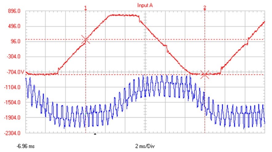
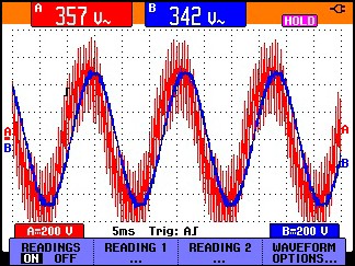
The figure below shows the relationship between the Uthd, line voltage and current waveforms and THDu on a 560kW6 pulse VFD. Note the high frequency components in the line voltages.
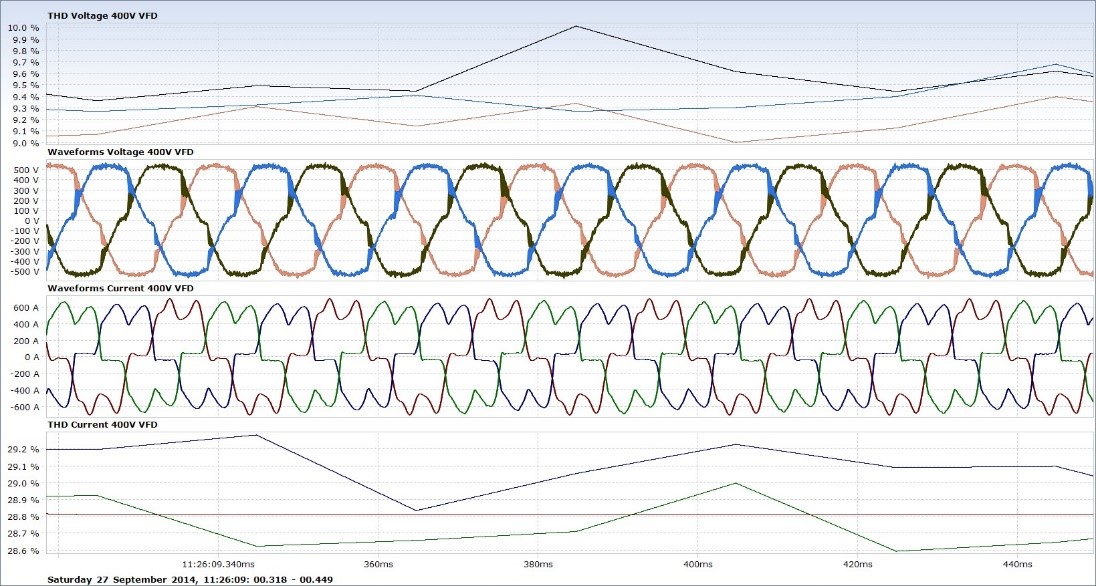
Note : VFDs, without AC line or DC bus reactance have 85-135% Uthd. In this instance 3% AC line reactors were installed in the VFD. The Ithd was around 28-24% based on generator subtransient reactance (X”d) of around 16-18%. Since the harmonic voltage distortion (Uthd) is a function of the harmonic current being drawn by the non-linear load(s) it will be obvious that Uthd will be reduced slightly if AC line reactors are installed. 3% reactance is a comprise between cost, size and performance and will permit active filters to be used for harmonic mitigation, if required. At least 3% AC line reactors are essential if active filters are to be used for harmonic mitigation on VFDs, 4% if SCR drives and other rectifier loads.
Rigs built in recent years tend to have VFD based drilling packages and usually have some type harmonic mitigation installed in an attempt to comply with marine classification bodies rules. However, this may not always the case unfortunately. Proper compliance or verification testing is rarely carried out during trails or work up.
Common mode voltage
Over the last 5-10 years the use VFDs have increased tremendously on offshore/onshore installations and drilling rigs. This popularity however as resulted in a dramatic increase in a phenomenon of “common mode voltage” also known as “common mode shift”, which can have serious consequences on the operational integrity and safety of electrical other equipment.
Common mode voltage originates at output of VFDs due to the non-sinusoidal and high du/dt (i.e. rate of rise of voltage) characteristic of the rapidly switched output voltages as illustrated in Fig 10. The PWM (pulse width modulated) outputs from VFDs results in most EMC problems.
Excessive common mode voltage (CMV) can disrupt sensitive electronic equipment resulting operational serious operational problems. CMV is considered by many as the ‘IED’ of the offshore and oilfield electrical world. Highly disruptive to susceptible equipment, it is rarely measured and can occur on any installation which has VFDs. The cause is often the incorrect installation of VFD equipment from an EMC (i.e. electromagnetic compatibility) perspective.
Common mode voltage (CMV) is an EMC (electromagnetic compatibility) issue. It can be measured between each phase and ground using an oscilloscope and spectrum analyser or a suitable PQ recorder. An explanation of common mode voltage is complex and outwith the remit of this section but a detailed explanation can be found in the Resource section of this website via the paper, “AADE-11-NTCE-7 The Price of Poor Power Quality”. Click here to download a copy of AADE-11-NTCE_7_The Price of Poor Power Quality_Evans IC & Richards MJR_Rev 5_20th March 2011
‘EMC’ covers electromagnetic phenomena over a very wide range of frequencies; the European EU Directive limits the frequency range from 0Hz (DC) to 400GHz. North America has its own standards via the FCC Regulations.
VFDs are powerful emitters of electro-magnetic noise due to the rapid switching of output voltage and current. SCRs, as used in DC drives are benign by comparison, switch relatively slowly, limiting their emission spectrum to around 1MHz. VFDs which use IGBTs emit frequencies up to around 50MHz with most problematic emissions in the range 1-150kHz (for VFDs).
In the European Union there is a legal requirement to use specially designed EMC filters designed for 150kHz- 30MHz. Variable speed drives must also be installed in strict compliance with the drive manufacturer’s EMC instructions (e.g. specific type of cable, cable routing, enclosure design and layout, grounding and bonding, etc.) to minimise emissions of EMI. Common mode EMI problems due to VFDs usually occur below 150kHz (i.e. usually 1-15kHz) and may require special filters and techniques.
The majority of offshore power installations are IT networks (i.e. isolated neutrals). These networks cannot use standard EMC filters since the filter capacitors have to be connected to ground and are destroyed should a ground fault appear on the system.
‘Floating’ EMC filters may be used with caution but this often raises causes safety concerns and successful implementation requires considerable EMC expertise and experience. Isolation transformers with electrostatic shielding can be very effective but also large and expensive. In some cases, capacitors to earth can be utilised to provide some, if inelegant, attenuation.
In addition to the conductive paths in a VFD (Fig 12), the common mode voltages and currents flow between the phases and ground through any stray capacitances [e.g. cables, motor/generator windings] to the grounded metalwork (e.g. the hull of a rig).
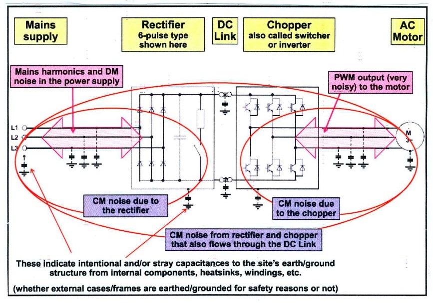
The higher the frequency, the lower the impedance of the stray capacitances, which means that the VFD switching ‘noise’, consisting of very brief transient ‘spikes’ at the switching instants easily pass through the stray capacitances.
Common mode currents flow through cable insulation, through the air and through the metal structure of the hull and any item of electrical equipment connected to it. Installing EMC filters (i.e. ungrounded types) or isolating transformers at the VFD input essentially provides a shorter path for common mode currents so they flow through less items of equipment, thus sparing their control systems the EMI exposure and subsequent problems which may result.
Some examples of the problems caused by common mode voltage/current follow :
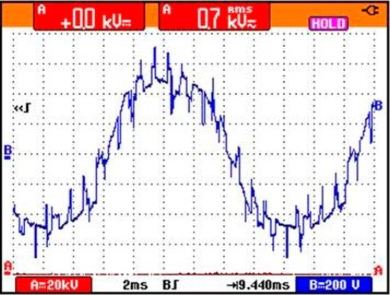
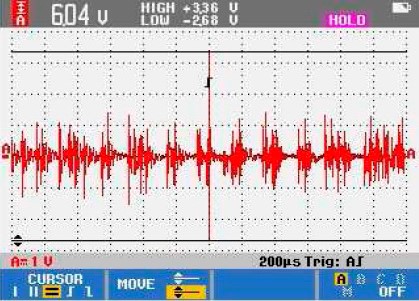
Example One. This involved a jack-up rig with a hybrid drilling package (i.e. SCR drives for mud pumps and VFDs for draw-works and top drive). The red trace in the figure below represents the Phase One to ground voltage when no drilling package VFDs are assigned or running. All equipment on the MODU operated without any problems during this period.
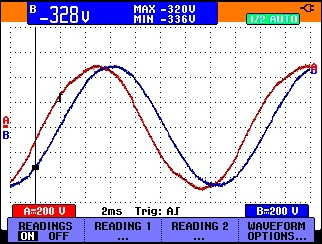
In the figure below the red trace represents the Phase V1 to ground voltage when either of the drilling package VFDs were assigned or running. The consequences of the voltage rendered all three deck cranes ‘dangerous’ as the common mode voltage interfered with the crane electronic control systems and other equipment. The rig was taken off contract until the problems could be resolved.
The common mode voltage spectrum can be seen at 153V at 1.98kHz (i.e. switching frequency of the VFDs); the highest recorded voltage was 203.54V between phase and ground at 1.98kHz.
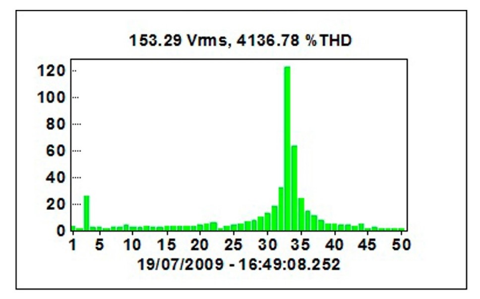
Note that the 3rd harmonic voltage in the above voltage spectrum is due to the dissimilar pitch phenomena which occurs when generators are paralleled.
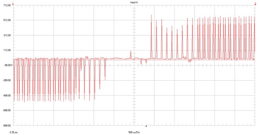
Example Two. This example illustrates the effects of common mode voltage on the operation of a jack-up fire and gas detection system. The left trace illustrates the control pulses when the system operated normally. The right trace illustrates the result when a new 1200HP/900kW pump VFD was connected to the system.
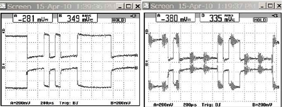
When the new pump VFD was operating (right trace) the fire and gas detection system faulted continuously, resulting in spurious gas alarms and was disabled until the cause of the failures were established and the system made fully operational again. This left the rig and the personnel at risk for days.
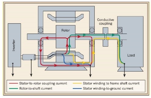
Example Three. The path for common mode voltage, seen below and current is from the VFD IGBT output bridge, along the cables to the motor, across the air gap to the rotor and via the bearings to ground (i.e. the hull if offshore or the ground if a land-rig).
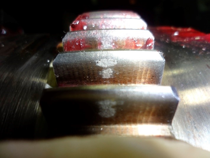
The figure below illustrates the effect of excessive common mode voltage through electrostatic discharges (ESD) on a 2500kW marine shaft generator with VFD voltage controller. The cause of the damage to the flexible coupling and bearings was incorrect EMC installation procedures and practices.
The effect of common mode current and AC motors
Above we have only considered the disruption to equipment due to common mode voltage. However, the associated common mode current can be a serious problem for the AC motors connected to VFDs AND to fixed speed motors (where VFDs are present) which are connected to the same ground (e.g. the hull. The high frequency common mode current transits from the VFD IGBT inverter stage along (and outside) the connecting cable to the motor. The common mode current is constantly looking for a ground and finds it via the motor bearings where the bearing(s) is damaged/destroyed by EDM (electrical discharge machining).
The path for common mode current is show below.
Note : Excessive common mode voltage/current and electrostatic discharges (including EDM) are serious issues for all VFD fed explosion-proof motors due to potential damage to bearings and flame paths. In addition, high frequency components in VFD waveforms can result in “hot rotors,” which on rotor critical machines can result in dangerous high rotor surface temperatures, well outside the temperature class.
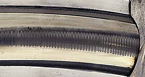
Common mode current can also damage and destroy the bearings on fixed speed AC motors. The illustration below shows an example of the effects of EMD due to micro-arcing (at VFD switching frequencies) on >1000kW MV EExd motors due to the common mode voltage/current produced by multiple, large PWM VFDs. In this case motor(s) bearing life did not exceed 1400-1600hrs.
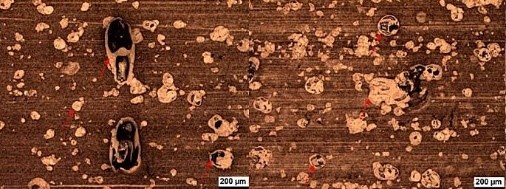
The common mode current micro-arcing also a serious potential danger if gas, vapour or condensate is present in the hazardous area. Common mode current can be doubly dangerous in EExd (flameproof) motors as any bearing damage may affect the flameproof paths with potentially catastrophic results.
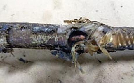
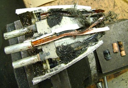
ESP cable and connector damage due to common mode issues
Due to the very long cable lengths associated with VFDs on ESP (electrical submersible pump) applications, common mode voltages and currents can be very problematic. Two examples of the damage to ESP cables and connectors, either as a direct or contributory factor by common mode current, are illustrated below.